Copper busbar flatness inspection should evaluate a clearly identified functional surface under agreed support and measurement conditions. Begin with the drawing, distinguish local contact-pad flatness from overall bow or twist, and choose a method capable of resolving the specified tolerance. Record the measured area, point coverage, part condition and instrument uncertainty. A smooth-looking face, a single straightedge check or a bolt that pulls an assembly together does not establish that the required geometry is acceptable. The inspection result must be interpreted alongside surface condition and joint design, rather than treated as a stand-alone prediction of electrical performance.
Define the surface that actually matters
A copper component may contain contact pads, bends, mounting holes, unsupported lengths and an insulating carrier. These features perform different jobs. An overall shape measurement may be important for installation, while a local contact region needs a separate geometric requirement. State which surface is controlled and show its boundaries on the drawing or inspection sketch.
Flatness describes variation of a surface relative to an ideal plane. It is different from the orientation of that face relative to another feature. If the design needs two pads to align, a mounting hole to locate a component or a face to remain parallel to a datum, those requirements need their own interpretation. Do not ask one flatness number to represent all assembly relationships.
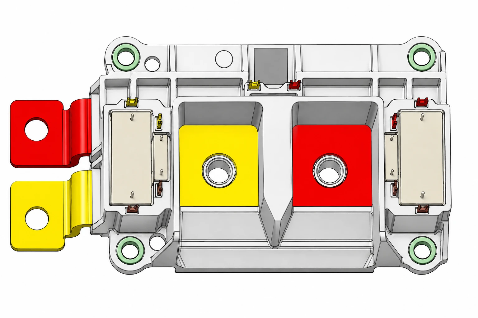
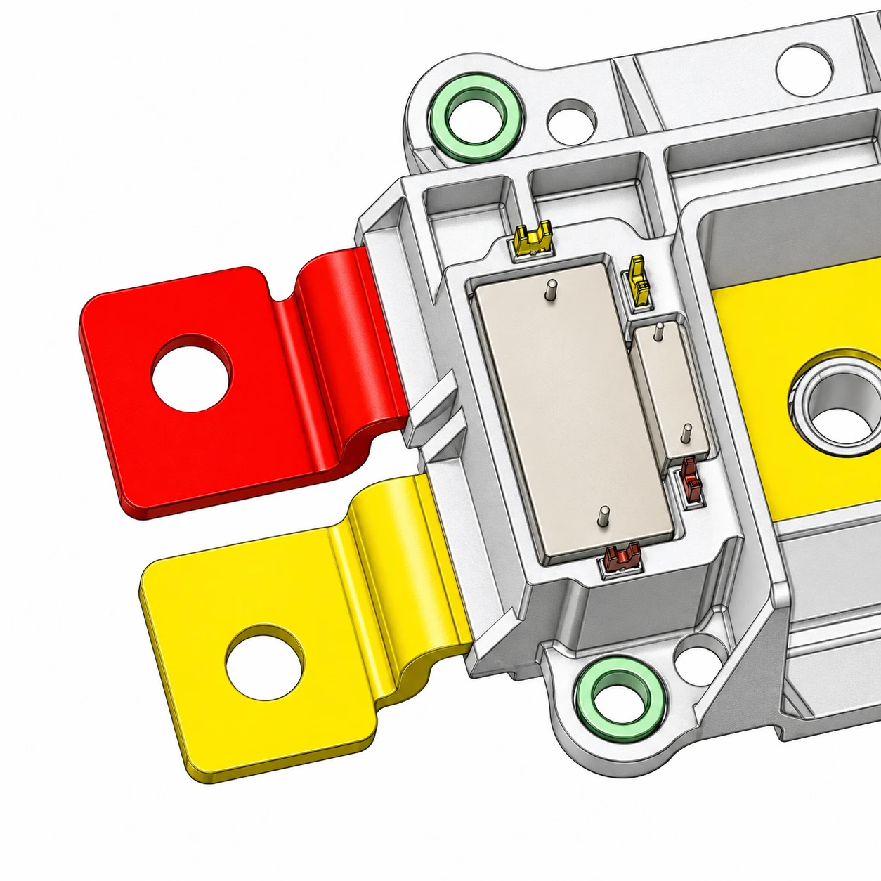
For a real product discussion, the BM001139 catalogue assembly shows separate colored pads and projecting tabs within a carrier. The image helps identify regions to discuss with the supplier, but it does not supply dimensions, material certification, surface tolerances or an approved measurement plan. Request the current assembly and component drawings before assigning a requirement to any visible region.
Keep flatness, roughness and cleanliness separate
Flatness concerns the form of a surface across a defined area. Roughness concerns smaller-scale surface texture evaluated using its own method and settings. Cleanliness concerns contaminants or residues. A polished surface can still be bowed, and a geometrically acceptable surface can still be unsuitable for assembly because of damage or contamination.
The Copper for Busbars technical handbook discusses contact surfaces and pressure as parts of joint performance. It explains that electrical contact occurs at discrete locations within the apparent interface. This supports evaluating geometry together with the approved surface preparation and clamping arrangement; it does not establish a universal flatness tolerance for every copper assembly.
Do not polish, scrape or abrade a finished component merely to improve an inspection result. Surface treatment may be part of the design, and removing it can change the product. Inspect the specified delivery condition and use only an approved cleaning procedure. Record any debris, coating damage or raised edge separately so that geometry and surface-condition findings remain distinguishable.
Select a measurement method from the requirement
For an accessible rigid face, a suitable reference surface and indicator arrangement can support a defined comparative inspection. The method needs controlled support positions, adequate point coverage and a clear calculation procedure. The highest minus lowest raw indicator reading may include setup tilt; it is not automatically the drawing’s required flatness evaluation.
A coordinate measuring machine can sample a surface and evaluate its form with an approved strategy. Probe size, point distribution, edge exclusions, fitting method and part support all affect the result. A detailed report should preserve those choices. A sparse set of points can miss a local high spot even if the equipment has excellent nominal accuracy.
A straightedge and feeler gauge may be useful for screening a defined gap along an accessible line. That does not necessarily characterize the whole surface. Label the result according to what was actually checked, and use a more complete method when the drawing or decision requires it. Avoid upgrading a quick visual or line check into a full geometric acceptance statement.
| Inspection approach | Useful purpose | Condition to document |
|---|---|---|
| Visual examination | Locate contamination, obvious damage and raised edges | Lighting, accessible areas and photographs |
| Straightedge gap check | Screen selected lines for a defined assembly concern | Line location, reference tool and applied force |
| Indicator-based comparison | Map an accessible supported face using an approved setup | Reference, support points, coverage and tilt treatment |
| Coordinate measurement | Evaluate surface form and related drawing features | Sampling strategy, probe, fitting and uncertainty |
| Assembly verification | Check fit in the specified installed arrangement | Fixture, fasteners, sequence and acceptance criteria |
The table outlines measurement choices rather than prescribing equipment for a particular tolerance. The supplier and buyer should agree on a method before using results to accept or reject a lot. If two methods disagree, compare their setups and definitions before concluding that one batch changed shape.
Control support, restraint and temperature
Long, thin or formed parts can change apparent shape when their supports move. Clamps can also force a component toward the fixture. Define whether inspection occurs in a free condition, under specified restraint or as part of an assembled unit. These are different measurement conditions and should not share an unexplained acceptance number.
Record support locations on a sketch and identify the orientation of the part. If a probe or indicator contacts the surface, consider whether its force can deform the feature being measured. A compliant tab may need a different inspection arrangement from a thick pad. Ask the metrology team to demonstrate repeatability by removing and replacing a representative sample.
The NIST-authored paper Uncertainty and Dimensional Calibrations describes contributions from temperature, mechanical deformation and instrument geometry. Those are general measurement principles, not busbar acceptance limits. They explain why instrument resolution alone cannot establish that a result is reliable enough for a tight manufacturing decision.
Allow the part and measurement system to reach the specified environmental condition. A component recently handled, processed or moved from another area may not yet be stable. Record the relevant temperature conditions when required by the inspection plan, particularly when comparing results from different laboratories or different production stages.
Make the report reproducible
A useful measurement report identifies the part number, revision, batch, inspected face and final manufacturing condition. Include the instrument and calibration status, setup sketch, point map, calculation method and measured result. Where uncertainty affects acceptance, state the agreed decision rule rather than leaving the inspector to improvise at the tolerance boundary.
Retain enough raw data to investigate a disputed result. An isolated pass stamp gives no indication whether the entire pad was measured, whether a hole-edge area was excluded or whether the part was clamped. Photographs showing the sample supported in the measurement setup often resolve questions that a spreadsheet of final numbers cannot.
Compare like with like when tracking process changes. Measurements before forming, after forming and after finishing describe different stages. If a supplier corrects a part, preserve the initial result and document the approved rework and final check. Do not silently replace an out-of-tolerance measurement with the best reading from repeated setups.
Connect geometric evidence to joint performance carefully
Flatness is one part of joint quality. Electrical resistance and temperature rise also depend on the complete connection, including contact arrangement, pressure, surface condition and operating environment. A geometric pass therefore does not prove a current rating or guarantee that a joint will stay cool in service.
Use the separate busbar bolted-joint review guide for questions about fasteners and assembly evidence. A flatness investigation should remain focused on the measured surface and its specification. Increasing tightening torque to hide a fit problem can change the mechanical condition without resolving the original geometric concern.
For further background, the NPTEL lecture below explains straightness, flatness and squareness measurement. It is an educational resource for understanding the distinctions between geometric features. Its demonstrations do not define the tolerance or fixture appropriate for the BM001139 assembly or any other supplier part.
Watch Measurement of straightness, flatness and squareness on YouTube
Send a drawing-based inspection request
Give the supplier the current drawing, highlighted inspection area, intended assembly condition and required report format. Ask when the measurement occurs in the manufacturing sequence and whether the final surface treatment is included. Define the sampling plan and escalation procedure through the project’s quality agreement rather than borrowing numbers from a general article.
Include identification requirements so that the report can be linked to delivered parts. The busbar identification and traceability guide provides a complementary way to connect drawings, batches and inspection records. For a broader discussion of component selection, see the copper busbar overview.
When a supplier cannot confirm a flatness requirement, identify the unresolved issue explicitly: unclear surface boundary, unsuitable support, missing method capability or absent drawing tolerance. Resolve that item before release. A narrower, agreed requirement on the functional contact area is usually easier to verify than an unexplained demand for a perfectly flat complete assembly.
Frequently asked questions
Is there one copper busbar flatness tolerance for every product?
No. The acceptable geometry depends on the drawing, functional contact area and assembly design. Use the requirement approved for the specific part and measurement condition.
Does a smooth surface prove good flatness?
No. Surface texture and surface form describe different features. A smooth face can still be bowed or twisted, so check each requirement using the appropriate method.
Can tightening bolts replace a flatness inspection?
No. Bolts can change the part’s shape and loading. Assembly verification may be required, but it does not replace the drawing-defined geometric inspection.
Why do two laboratories report different results?
Compare the inspected area, support positions, restraint, temperature, sampling and calculation method. Differences in those conditions can produce different results even on the same component.
What should accompany a flatness result?
Include part and batch identity, drawing revision, measured area, setup, method, result and relevant uncertainty or decision rule. These make the acceptance decision traceable.