


Copper busbar marking should distinguish circuit function, part identity, and production traceability while keeping electrical contact areas clear. Start with the approved schematic and applicable equipment requirements, define a marking zone on the drawing, and qualify the chosen label, printing, engraving, or stamping process for the actual finish and environment. A color band or stamped number does not establish current capacity, copper grade, or permission to modify a certified assembly. This guide gives buyers and engineers a practical way to specify, inspect, and document busbar identification.
The scope here is identification of manufactured copper conductors and assemblies. It does not replace busbar sizing, electrical design, or safe isolation procedures. Before any inspection or marking of installed equipment, qualified personnel must follow the equipment’s isolation and verification process. An unidentified conductor should be treated as unresolved until its function is confirmed from controlled documents.
Use three separate layers of busbar identification
A useful marking system answers three questions: which conductor is this in the circuit, which manufactured configuration is it, and which production records belong to it? Combining all three into an unexplained string makes field service and incoming inspection harder. Define the purpose of each field and connect it to a record that a technician or inspector can retrieve.
| Layer | Typical information | Controlling evidence | Common mistake |
|---|---|---|---|
| Circuit function | Phase, neutral, protective function, or DC polarity where applicable | Approved schematic and the applicable identification rules | Assigning function from copper appearance or an unrelated color chart |
| Manufactured identity | Part number and revision or configuration reference | Released drawing and bill of materials | Using a batch number as the orderable reference |
| Traceability | Lot, date, supplier, or serial identifier as specified | Traveler, material record, and process records | Printing a code that cannot be linked to retained evidence |
| Assembly restrictions | Specific manufacturer-defined connection or service information | Equipment instructions and evaluated construction | Assuming an existing hole permits a new tap connection |
The fields above are a practical documentation structure. Their exact content and location must come from the equipment specification. The general framework for identifying conductors and terminals is covered by IEC 60445, including the 2026 amendment; use the edition required for the actual project and destination market.
Functional identification is not a universal color recipe
Do not publish or apply one phase-color chart as though it covers every country, voltage system, and equipment type. Establish the applicable requirements first, then copy the approved notation into the drawing and inspection instruction. Where alphanumeric identifiers are used, their meaning must agree with the schematic. A conductor marked for a protective function must actually have that function in the design.
For a DC assembly, define positive and negative references from the released circuit documentation. Do not infer polarity from an insulated cover’s color or the position of a copper tab. Also distinguish the marking on a removable cover from identification of the conductor below it. The assembly process should prevent a cover from being reinstalled over the wrong conductor.
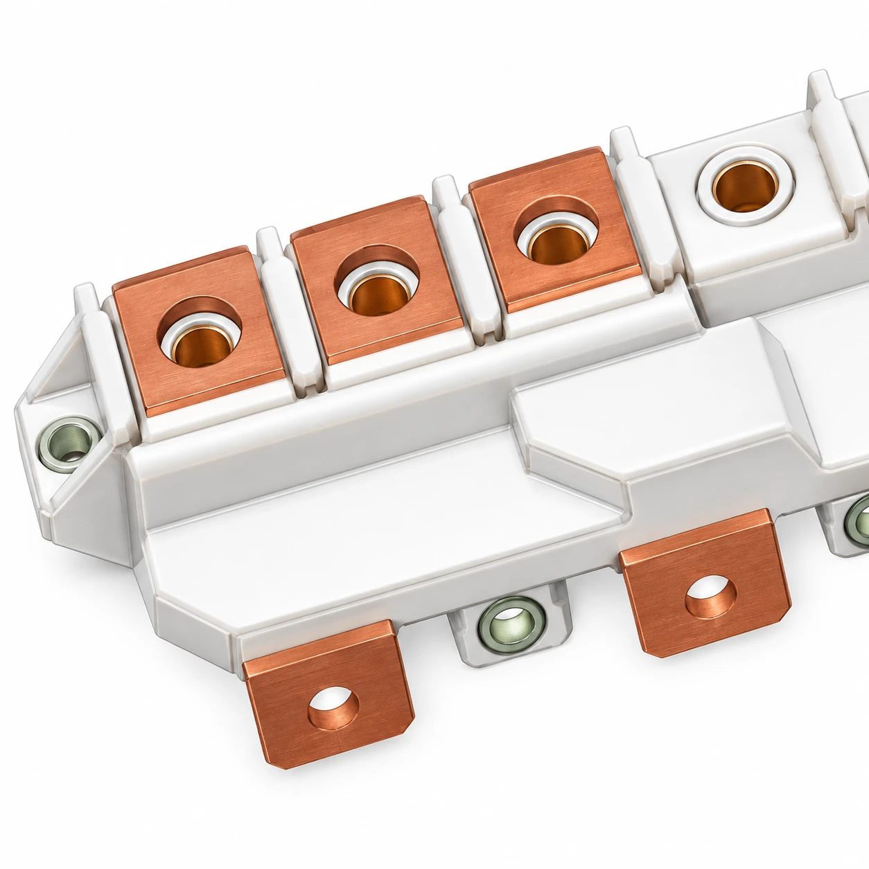
Compare labels, printing, laser marking, and stamping
The best marking method depends on where the information needs to remain readable, the surface condition, the manufacturing sequence, and the consequences of rework. Start by defining the required identification and available space. Selecting a machine first can force the engineering team to accept a poor location or an unnecessary change to the conductor.
| Method | Useful application | Main verification points |
|---|---|---|
| Adhesive label on an approved surface | Long text, machine-readable traceability, or assembly identification | Adhesion, material compatibility, installed temperature, cleaning exposure, and visibility |
| Ink printing on an approved area | Short repeated identifiers in a controlled production process | Contrast, cure, smearing, abrasion, and resistance to the specified fluids |
| Laser marking or engraving | Permanent direct identification where the process is approved | Legibility, depth or surface change, finish integrity, heat effects, and corrosion assessment |
| Mechanical stamping | Short identifiers on a drawing-approved robust zone | Deformation, burrs, tool support, dimensional change, and remaining conductor section |
| Insulation or adjacent marker | Functional identification without marking a contact pad | Retention, position after assembly, compatibility with the insulation system, and unambiguous association |
This is a selection checklist rather than a ranking of guaranteed durability. No method is automatically suitable for every copper grade, coating, or service condition. A direct mark may survive handling well yet disturb a critical surface. A label may preserve the metal surface yet fail if its adhesive is unsuitable for the operating environment.
Plated surfaces require a process-specific review
Agree whether direct marking occurs before or after plating, and include that sequence in the process plan. Marking through a coating can expose underlying material or create a surface condition that differs from the approved sample. Plating after marking can also affect contrast or legibility. Request first-article evidence that reflects the actual order of operations.
If the drawing specifies a coated conductor, do not replace the finish locally just to improve contrast. The marking proposal should be reviewed together with corrosion exposure, handling, and joint requirements. For the finish-selection question itself, see the existing tin-plated copper busbar guide. The new identification instruction should reference the approved finish rather than redefine it.
Where should the mark go?
Show an allowed marking zone and keep-out areas on the drawing. Protect contact pads, fastener seating surfaces, sealing interfaces, critical bends, and insulation boundaries unless the design specifically permits marking there. The precise zone needs engineering approval; there is no universal distance from a hole or edge that makes every process safe.
A useful zone remains visible after installation and does not become ambiguous when several conductors are close together. Check it with the actual mounting bracket, cover, lug, and cable routing. If the only permanent code is hidden beneath a cover, the assembly may need an approved secondary identifier that remains readable without disturbing the electrical joint.
Keep cleanliness separate from identification. Ink, adhesive, abrasive residue, or metal debris must not contaminate contact areas. For US workplaces within its scope, OSHA 1910.303 addresses equipment marking durability and protection of internal electrical parts from damaging contamination. That supports reviewing the marking process and installation instructions together; it does not authorize painting a busbar indiscriminately.
Do not drill a new hole just to attach a tag
Removing conductor material or adding hardware can affect the design. An identification tag must use an approved attachment method. Do not assume an unused hole is available for a tag, a new terminal, or a tap connection. Its function may be limited by the equipment construction and installation instructions.
In its guidance for panelboards and deadfront switchboards, UL explains the significance of factory-designated tap provisions and field modifications. That guidance is specific to the equipment discussed. It is a useful reminder to seek the manufacturer’s authorization rather than extending a marking task into an unreviewed electrical modification.
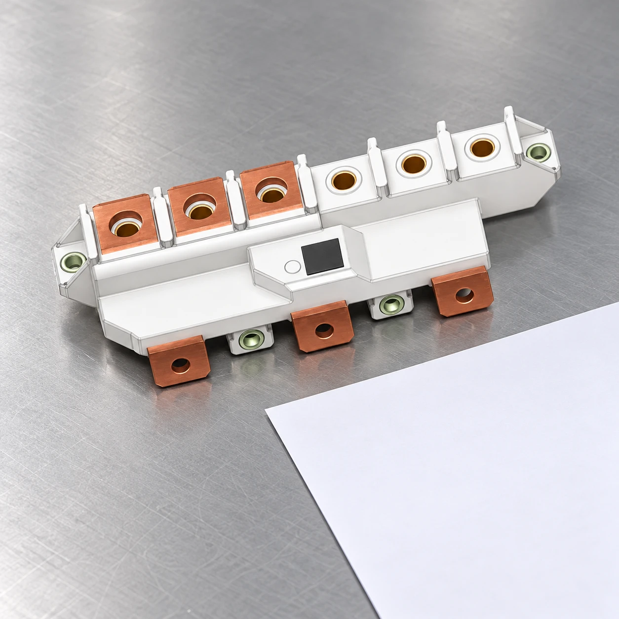
What to specify on the drawing and quotation request
A complete marking note defines the data, method, location, orientation, readability criteria, and supporting records. If any element is left to supplier discretion, state the approval process for that choice. Otherwise two quotations may include different marking processes even though both suppliers believe they meet the same requirement.
- Data content: identify the required part reference, revision policy, lot or serial field, and any functional notation. Define which data belongs on the part and which belongs on its packaging.
- Location and orientation: show the permitted zone and viewing direction in the installed condition. Mark contact and other critical keep-out areas clearly.
- Process and sequence: name the permitted method or request an approval sample. State how forming, cleaning, plating, insulation, and marking fit together.
- Acceptance: agree legibility, contrast, correct content, scan requirements if used, and absence of process damage. Use application-specific limits rather than a generic online template.
- Records: define the link from the code to material and manufacturing records, retention expectations, and how the buyer can retrieve the evidence.
- Change control: define which data, location, equipment, material, or process changes need approval before production.
For example, an illustrative lot structure might combine a production-date field with a batch sequence. It should be described as an internal convention, not an ISO requirement. Check that the code stays unique over the required retention period and that leading zeroes survive the purchasing and warehouse systems. A short human-readable code can accompany a machine-readable symbol if the drawing permits both.
For a Shenji enquiry, attach the conductor drawing and explain the installed assembly. Review the copper busbar product directory as a starting point, then request confirmation of the exact product, available marking process, and evidence through the project enquiry page. The product illustration in this article does not promise a particular marking capability or rating.
Inspect the marked part and the record behind it
Inspect content first: does the physical identifier match the drawing, packaging, and production record? Then inspect execution: is it readable in the specified orientation, inside the approved zone, and clear of functional surfaces? Record both questions. A perfectly printed wrong part number is still a failure, while the correct code placed under a joint may be unusable.
Qualification should reflect the actual environment. Consider handling abrasion, cleaning, temperature exposure, relevant fluids, and service access when defining a test plan. After the agreed exposures, check readability and any surface or dimensional change. Do not invent a universal rub-test count or laser depth; those limits must be chosen and justified for the product and process.
On receipt, use sampling and acceptance rules agreed with the supplier and your quality system. Escalate unreadable codes, duplicates, missing records, and marks outside the approved zone. Corrective work should follow an approved instruction. Do not grind away a mark, restamp the contact pad, or cover a discrepancy with a new label without evaluating the consequences.
For related engineering decisions, the copper busbar specification guide covers material, geometry, and assembled-path validation, while the flexible copper busbar guide addresses the different mechanical interface. Marking should support those specifications, not replace them.
Video: understand the conductors inside an electrical panel
Main electrical panel explained – Load center – service panel from The Engineering Mindset provides visual background on panel conductors and their functions. Its examples use a particular installation context. Use it to understand the arrangement, then apply the actual project drawings and local requirements when specifying identification.
Watch Main electrical panel explained – Load center – service panel on YouTube
Frequently asked questions
Does a copper busbar need a part number and a circuit label?
They serve different purposes. A part number identifies the manufactured configuration; a circuit label identifies its function in the assembly. The equipment specification determines which identifiers are required and where they belong.
Can a busbar be laser marked after tin plating?
Only when the process and location are approved for that product. Review changes to the coating, exposed material, legibility, corrosion behavior, and contact surfaces using a production-intent sample.
Is there one universal copper busbar color code?
No single chart should be applied across all markets and equipment types. Use the applicable identification requirements and approved schematic for the specific assembly.
Can I stamp a number beside a connection hole?
Use only a drawing-approved location and process. Stamping can deform material or create burrs. Its effect on the conductor, joint seating, and clearances must be assessed.
Does a marking prove the busbar current rating?
A marking records an identifier or a declared rating. It does not itself establish performance. The rating needs supporting design and verification evidence for the actual assembly and operating conditions.






