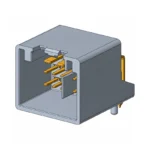


Connector stress relaxation is the reduction of stress over time while a contact element remains at a prescribed deflection. For a spring contact, that can reduce the force maintaining the electrical interface. Review the alloy, temper, formed geometry, mating condition, temperature and exposure duration together; a material name or an initial force result is not enough. Useful supplier evidence connects the tested specimen to the production contact and explains how remaining force was measured. This guide focuses on evaluating that evidence. It does not assign a temperature rating, lifetime or force limit to a catalogue terminal without a released specification and configuration-specific validation.
Distinguish stress relaxation from other contact problems
A spring contact is deflected when it engages its intended mate. The design relies on the resulting mechanical force to maintain the interface. Stress relaxation concerns a time-dependent reduction in stress at the prescribed deformation. It is different from simply measuring a low insertion force, observing plating wear or finding that a terminal was never seated correctly. Those conditions can coexist, but they require different evidence and corrective action.
The Kupferverband guide to stress relaxation of copper alloys explains the phenomenon and discusses why specimen methods and processing history matter when applying material data to components. Its practical implication is that a generic alloy curve should be treated as supporting information, rather than as a finished-contact qualification. Record the curve’s conditions before comparing it with an application.
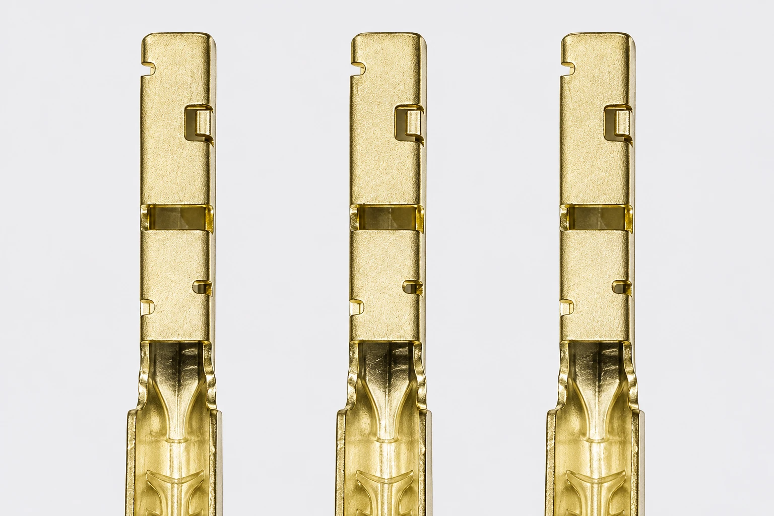
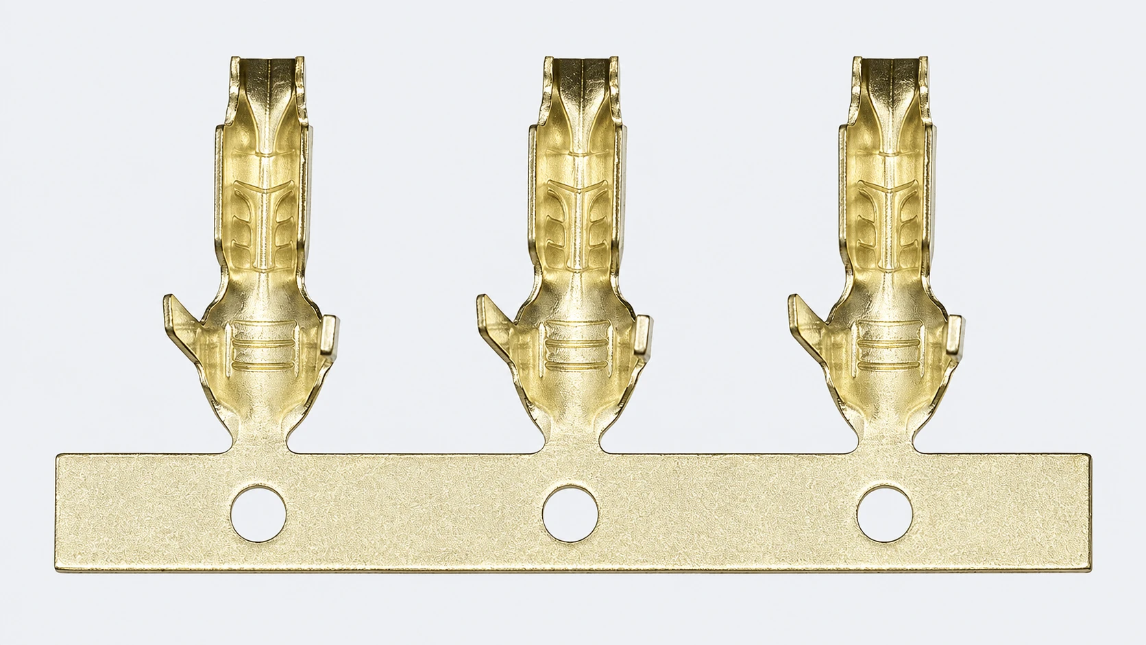
The 305-2107S catalogue terminal strip provides a visible example of formed contact parts. Its gold-colored appearance does not identify an alloy, plating chemistry or spring-force rating. The image also does not reveal every internal contact surface. Obtain the controlled product drawing and material documentation before attributing stress-relaxation performance to this or any other catalogue terminal.
Separate the mating interface from the wire termination
A contact’s mating function and its crimped wire connection are different interfaces. A strong wire pull result does not establish retained normal force at the mating surface. Conversely, a contact-force result does not validate the crimp. Use the terminal connector selection guide for the broader termination context, then request evidence specific to the function under review.
Connect the specimen to the production configuration
Start with the part number, revision and manufacturing lot. Ask for alloy designation, temper, material thickness and relevant forming or heat-treatment history. Where information is proprietary, agree on a controlled reference that allows changes to be tracked. A report using an unidentified “copper alloy” leaves the reviewer unable to determine whether its results represent the purchased part.
Next identify the mating component and its dimensional condition. The deflection applied to a spring depends on the geometry of both parts. A test at one mating size cannot automatically cover a different tolerance boundary. Ask which conditions were selected and why they represent the application’s mechanical demand. Do not assume that increasing initial force always improves the long-term result without considering other design constraints.
Fraunhofer IWM’s work on dimensioning connectors and electrical bonds describes the relevance of copper’s relaxation behavior under thermal and mechanical loading and the need for suitable material characterization. For a buyer, this supports asking how forming and the actual loading condition are represented. It does not endorse a particular terminal or replace its validation report.
Review the exposure and measurement plan before testing
A useful plan defines the initial condition, the applied deflection, exposure temperature, duration and measurement sequence. State whether the contact is held in a production housing, a representative fixture or a simplified material-test arrangement. Each can answer a useful question, but they do not demonstrate the same thing. A fixture that controls a strip specimen does not necessarily reproduce the constraints of a complete connector.
| Report item | What it establishes | Question if missing |
|---|---|---|
| Alloy, temper and processing identity | The material condition represented by the specimen | Can this result be traced to the production terminal? |
| Geometry and applied deflection | The mechanical starting condition | Was the intended mating condition reproduced? |
| Exposure temperature and duration | The stated thermal history | Does the application fall within the tested scope? |
| Force measurement method | The quantity and location actually measured | Is the result direct contact force or an indirect proxy? |
| Individual initial and final readings | Absolute force and sample-to-sample variation | Does an average conceal a weak specimen? |
| Acceptance rule and deviations | The basis for the disposition | Was the limit agreed before results were known? |
The checklist defines report completeness rather than a test standard. Use the specification named by the design owner for the actual method and acceptance limits. If the laboratory changes a fixture, specimen orientation or measurement sequence, document the deviation and obtain a decision on whether the data remain applicable. Do not silently compare results produced by different methods as though they were interchangeable.
Record when the force was measured
A force reading during hot exposure and a reading after cooling describe different conditions. Record the temperature at measurement, any unloading or remating, and the elapsed time before the reading. Removal from a fixture can alter the condition being investigated. The sequence should be repeatable and should explain how the initial baseline and later readings are related.
Keep environmental exposure distinct from measurement uncertainty. Temperature variation, force-sensor calibration, alignment and fixture compliance can influence a result. Ask the laboratory how those influences are controlled for the chosen method. Extra digits on a force display do not demonstrate that small differences between samples are meaningful. Borderline outcomes need an agreed decision rule, not selective rounding.
Interpret remaining force with the absolute values
A report may express remaining force as a percentage of the initial force. When this is the defined metric, the arithmetic is remaining force divided by initial force, multiplied by one hundred. Keep the original forces in the same units and record the conditions for both readings. A percentage alone conceals whether the initial force was suitable for the assembly.
For illustration only, if a specimen began at 2.0 N and later measured 1.5 N under the same defined measurement condition, its remaining-force ratio would be 75%. These invented numbers demonstrate the calculation and are not a product rating or an acceptance threshold. A different specimen starting at 1.0 N and retaining 90% would have a smaller final force despite its better percentage. Compare both absolute and relative results.
Do not infer full electrical reliability from that ratio alone. Review the electrical measurements and environmental sequence required by the connector specification. The article on fretting corrosion diagnosis addresses movement and surface degradation, which may interact with contact force but are not the same mechanism. Likewise, current derating review concerns thermal operating conditions and requires its own configuration details.
Avoid unsupported lifetime extrapolation
A shorter exposure at a higher temperature is not automatically equivalent to a longer service period at a lower temperature. Ask for the model, its validation range and the evidence that the relevant mechanisms remain comparable. A chart extended beyond its tested range should be identified as a prediction. Purchasing language should distinguish measured performance from modeled estimates and from unverified assumptions.
Also check whether the evidence concerns strip material, a formed loose contact or a completed connector. Material data can help select candidates and explain trends. Component tests address geometry and processing more directly. Assembly tests add the effects of housings, mates and installation conditions. Keep these levels visible in the report so a useful supporting test is not promoted into a broader approval than it supports.
Prepare a focused supplier evidence request
Send the intended part number, mate, temperature profile and mechanical configuration, together with the specification and revision. Ask for the applicable validation report, specimen traceability, individual results, force method, exposure sequence and acceptance criteria. State any tolerance boundaries or service conditions that need coverage. Where the existing report does not cover them, request a gap assessment before agreeing on additional testing.
Define change control as part of the request. An alloy, temper, thickness, forming tool or heat-treatment change can make an older report less representative. Ask the supplier to identify which changes require review and how the buyer will be notified. Preserve the approved baseline and its limitations in the purchasing record. This creates a clear reference for future lots without inventing a universal remaining-force requirement.
Further learning: the stress and strain foundation
The IIT Guwahati NPTEL lecture below introduces stress and strain, the foundation for understanding elastic preload and prescribed deformation. It is background education rather than a connector-relaxation test procedure. Use the released specification and qualified laboratory method for the actual evidence request.
Watch Lec 1: Introduction to Stress and Strain on YouTube
Frequently asked questions
Does stress relaxation mean the terminal has broken?
No. Stress can decrease while the contact remains intact. The question is whether the resulting force and other measured performance still meet the requirements for the specified assembly.
Can a wire pull test prove retained contact force?
No. A wire pull test evaluates the termination under its specified method. It does not directly establish the force at the mating contact interface after thermal exposure.
Is the highest remaining-force percentage always best?
No. Review the absolute final force, initial condition, geometry and electrical requirements as well. A percentage can look favorable while the final force remains unsuitable for a particular design.
Can alloy data qualify a finished connector?
Not by itself. Alloy data supports material assessment. The formed component, mating configuration and assembly conditions need evidence appropriate to the claimed performance.
What is the correct acceptance limit?
Use the limit in the released product or customer specification and its defined measurement method. No single force value or percentage can be applied to every connector design.