


Plastic connector markings identify different things: the housing material, a terminal position, a mold cavity, a production date, or a supplier part number. A code such as >PA66-GF30< describes a polymer compound; it is not enough to order a replacement connector. To identify a housing reliably, separate each mark by purpose, photograph the mating face and latch, then confirm the complete part number against a controlled drawing. This guide explains how engineering and purchasing teams can read the marks, avoid false matches, and prepare a useful identification request.
The distinction matters because similar-looking housings can use the same resin while accepting different terminals. Conversely, one connector family may include several approved material or color variants. A molded code is a clue that helps narrow the investigation. Compatibility and performance still depend on the particular housing, terminals, seals, mating part, and application documentation.
First separate material, part identification, and production marks
Before searching a number online, record its location and appearance. Is it inside angle brackets, beside a terminal cavity, on a round date indicator, or next to a supplier symbol? Photograph the entire housing as well as the detail. Keeping this context prevents an isolated digit from being mistaken for a product reference.
| Observed mark | What it can indicate | What to verify |
|---|---|---|
| PA66, PBT, or a compound code between > and < | Generic material identification | Exact resin grade and the approved material record |
| A long alphanumeric string | Possible housing, tooling, or customer reference | Supplier drawing and orderable part-number cross-reference |
| Small numbers at wire-entry cavities | Terminal position identification | Connector view, orientation, and circuit assignment on the drawing |
| A separate short number or letter | Possible mold-cavity or tool-insert identification | Supplier marking legend; format is not universal |
| A dial, arrow, or grouped date characters | Possible molding date or production identifier | Supplier decoding convention and shipment lot record |
| Logo or certification-related symbol | Responsible organization or a specific approval claim | Authenticity, covered product, and scope in the relevant record |
This table is an inspection aid, not a universal decoding standard. Suppliers use different tooling and traceability conventions. The material-marking framework comes from ISO 11469; a specific manufacturer’s legend is needed for its production identifiers.
Keep uncertain readings explicit. Record “possible 8 or B” rather than silently choosing one character. Side lighting and a second photograph at a different angle often help with shallow molded lettering. Do not scrape the housing or apply an unapproved solvent to make a mark easier to read; that can damage the surface and obscure the original evidence.
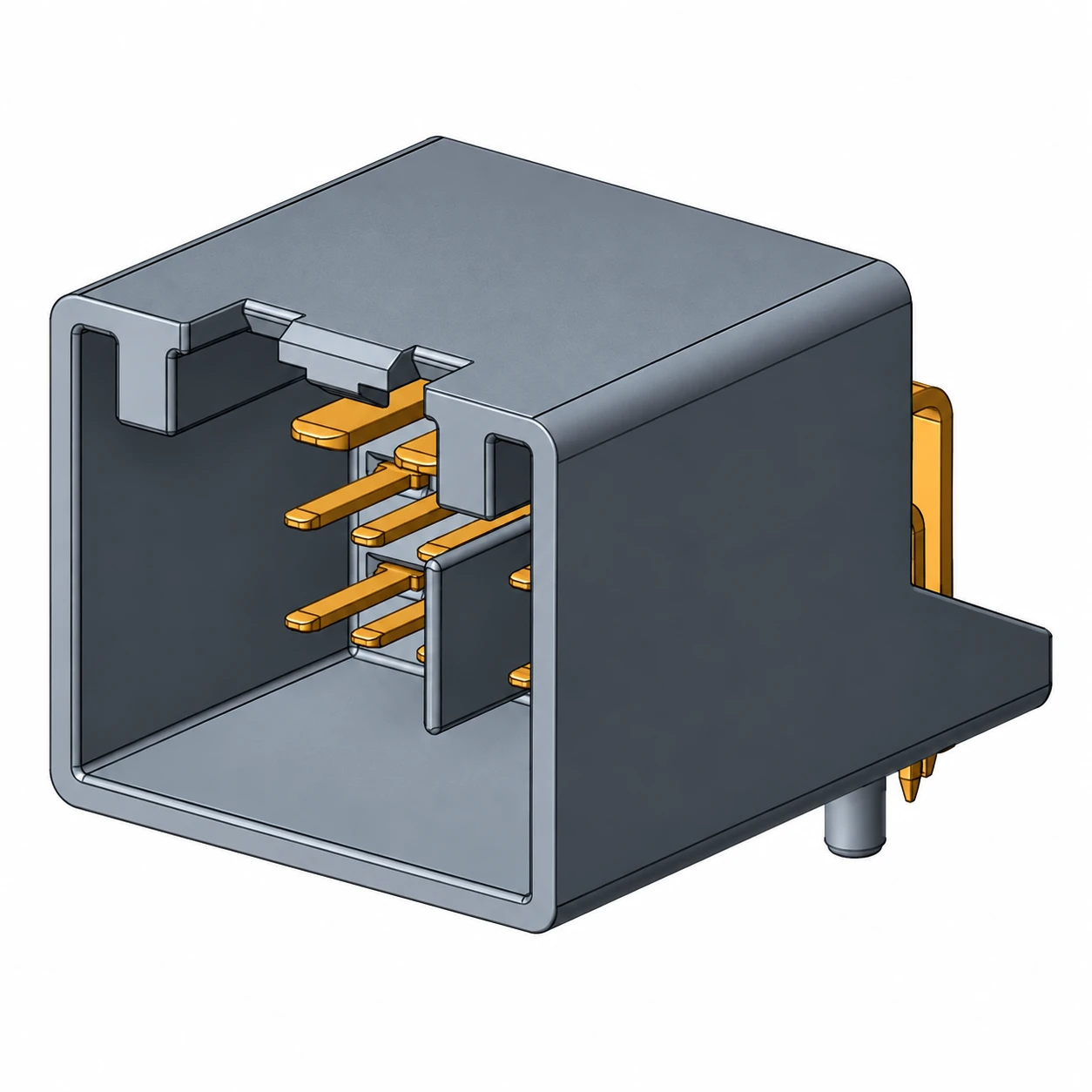
How to interpret PA66, PBT, and GF markings
PA66 identifies polyamide 66; PBT identifies polybutylene terephthalate. These are material-family abbreviations. ISO 1043-1 provides the system of polymer abbreviations, while ISO 1043-2 addresses filler and reinforcement symbols. The material family alone does not reveal the full commercial grade, additives, color formulation, processing history, or permitted service conditions.
In a conventional compound designation such as >PA66-GF30<, PA66 identifies the base polymer and GF30 denotes glass-fiber reinforcement at a nominal 30 percent by mass. Treat this as an illustrative decoding example, not as a statement about every Shenji connector. A housing with that mark can still differ from another PA66-GF30 housing in resin grade, geometry, terminal retention, or customer qualification.
A practical way to document the example is to enter “PA66-GF30, molded identification observed” in the sample record, then request the exact material specification separately. Do not enter an operating-temperature limit or flammability class unless the part documentation supports it. This preserves the difference between what the sample visibly says and what the application requires.
Website material descriptions can also combine information about several components. For example, the 2BK01-161228W-A product record lists a combined material description. That catalog wording is not evidence that the same string is molded onto the housing. Ask which portion describes the housing and which describes the conductive components, and obtain the current drawing before treating it as a material specification.
Why a polymer code does not establish flame performance
“PBT” or “PA66” is not a UL 94 classification. Even a familiar material family can contain grades with different recognition conditions. UL’s plastics-recognition terminology distinguishes the material designation, color, minimum thickness, and flame class. Review the actual record for the specified grade and conditions instead of transferring a claim from a different compound.
The same discipline applies to electrical ratings and environmental protection. A material code does not establish contact current, connector voltage, water ingress performance, or compatibility with a particular vehicle. Those questions involve the complete assembly. The waterproof automotive connector guide covers sealing and wiring considerations separately. The existing plastic wire connector selection guide explains the housing, terminal, cable, and seal interfaces; this article focuses on identifying the marks that support that review.
Part numbers, cavity numbers, and pin numbers are different
A housing part number identifies a defined configuration within a supplier’s system. A mold-cavity number helps trace which cavity produced a molded item. A terminal-position number tells the assembler which opening is which. Confusing these identifiers creates avoidable purchasing and wiring errors, especially when only a cropped photograph is available.
Consider two otherwise matching samples marked “2” and “5” on the outer wall. Those digits might identify different molding cavities rather than different connector versions. The correct action is to check the marking legend and dimensional drawing. Requiring identical production-cavity digits without evidence could wrongly reject acceptable stock; ignoring a real configuration difference could approve the wrong part.
Terminal-position numbering needs its own orientation check. A mating-face view and a wire-entry view look in opposite directions. Record the latch position and the viewing direction in the photograph. Never assign a circuit from a small molded number without consulting the connector drawing and wiring documentation. For the broader electrical interface, use the site’s wiring harness connector guide.
A six-step workflow for an unknown housing
- Record the context. Note the equipment, harness branch, mating component, and whether the sample is damaged. Follow the equipment’s safe isolation procedure before handling an installed connector.
- Photograph the useful views. Capture the mating face, wire entry, latch, sidewalls, and all markings. Include a scale in a separate clear image without covering key features.
- Transcribe marks by category. Separate material code, possible part number, position numbers, supplier symbol, and date or cavity marks. Preserve punctuation and uncertainty.
- Measure the interface. Record overall dimensions, cavity count, row arrangement, center spacing where measurable, key positions, and mounting features. Use a drawing for acceptance tolerances.
- Identify the entire mating system. Request the compatible housing, terminal, seals, secondary lock, and any approved release tool. Appearance alone cannot confirm contact-family compatibility.
- Approve against documents and a sample. Compare the current drawing, confirmed ordering reference, and trial assembly. Record who approved the match and which revision was used.
If the old connector is heat-distorted or its latch is broken, identify the damaged areas on the photograph. A supplier needs to know which dimensions may have changed in service. Sending only the intact-looking side can hide the feature that distinguishes one family from another.
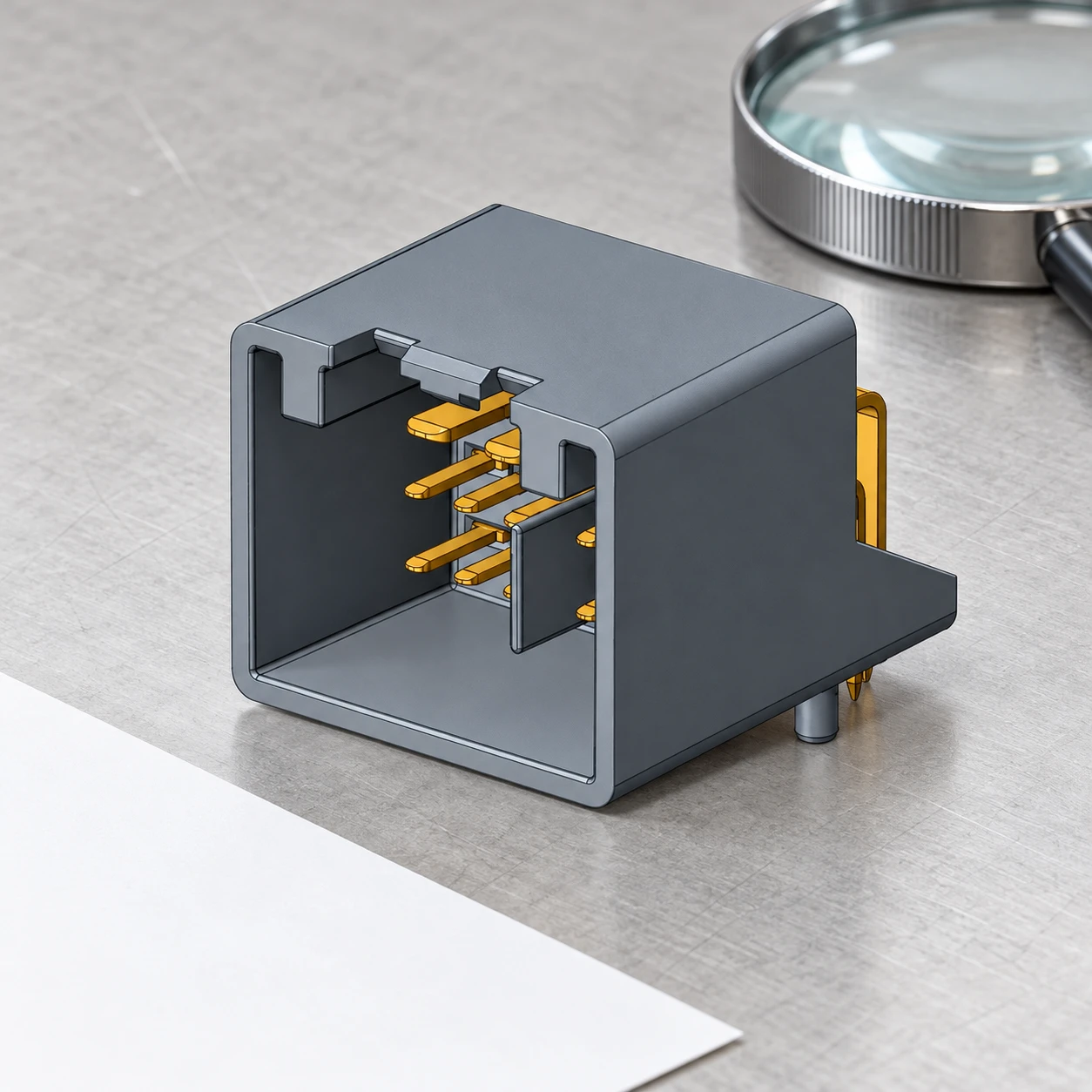
How to use markings during incoming inspection
An incoming-inspection instruction should state which identifiers must match exactly and which may legitimately vary. The approved housing reference and configuration may be fixed, while a production date or mold-cavity number can change between shipments. Tie each requirement to the purchase specification so inspectors can distinguish a product mismatch from normal traceability variation.
For each lot, retain the packaging label, supplier batch reference, sample photographs, drawing revision, and any requested material evidence. Confirm that the bag label and physical sample refer to the same product. A correct-looking label cannot compensate for the wrong keying, missing secondary lock, or incompatible terminal cavity.
Use a controlled response when a marking changes. Segregate the affected stock, compare geometry and supporting records, and ask whether the change reflects tooling maintenance, a new resin grade, or a different product configuration. Do not assume all marking changes require rejection, and do not assume all are cosmetic. The supplier’s explanation must be consistent with the approved configuration and change-control requirements.
What to put in a supplier identification request
A useful request includes the application, quantity, photographs, dimensions, every readable mark, and the required mating part if known. Add terminal and cable information when available. State the destination market and which documentation is needed. This lets the supplier respond with a defined candidate and a drawing rather than an unsupported assurance that two housings “look the same.”
Use a short acceptance statement such as: “Please identify an orderable housing and its approved terminal and mating references; confirm the drawing revision and explain the photographed material and cavity marks.” Attach the observed-mark record separately from the required-performance specification. Shenji’s engineering enquiry page is the next step for a model-specific review.
Video: why molded plastic carries process features
In Plastic Injection Molding, the independent educational channel engineerguy explains molding principles and the physical features the process leaves on plastic products. It provides useful background for inspecting a molded housing. It does not decode a particular connector’s supplier marks or establish its electrical suitability.
Watch Plastic Injection Molding on YouTube
Frequently asked questions
Is PA66 a connector part number?
No. PA66 is a polymer abbreviation for polyamide 66. Use the supplier’s confirmed housing reference, drawing, and mating-system information to identify an orderable connector.
What does GF30 mean on a plastic connector?
In a conventional polymer compound marking, GF30 denotes a nominal 30 percent glass-fiber content by mass. It does not identify the complete resin grade or establish the connector’s current, sealing, or flammability rating.
Can I replace a connector with another that has the same material code?
The material code alone is insufficient. Check cavity geometry, keying, latch, terminals, seals, mating part, dimensions, and application evidence before approving a replacement.
Does a different molded number mean the part is wrong?
It depends on the number’s function. A cavity or date identifier can change without changing the orderable configuration. Obtain the supplier marking legend and compare the approved part reference and drawing.
What if the housing markings are unreadable?
Send clear overall photographs, measured interface details, the mating reference, and any packaging or equipment information. Record damaged or uncertain features and ask the supplier to confirm identification against a drawing and sample.






