


Crimp height measurement checks a specified dimension of a formed terminal using a defined location, instrument and contact method. Compare the result with the approved specification for the exact terminal, conductor and tooling combination. Do not measure whichever surface is easiest to reach or use a universal height for all wires. A useful inspection record connects the reading to the parts, process settings and drawing revision that produced it.
This guide explains how to prepare a measurement plan, recognize misleading readings and use the results in process control. It does not supply a crimp dimension or tolerance for an unidentified terminal.
Identify the barrel and the dimension before measuring
A terminal can have separate features for conductor compression and insulation support. Their dimensions and inspection purposes differ. Establish which feature the drawing calls the crimp height, where the measurement is taken and which surfaces the measuring contacts should touch. A dimension measured on the insulation support cannot silently replace a conductor-barrel reading.
Open-barrel and other termination designs may require different measurement arrangements. Obtain a drawing or application instruction that illustrates the correct section. Do not copy a technique from a different terminal merely because the external shape looks similar. The inspection needs to match the formed product and the stated dimensional definition.
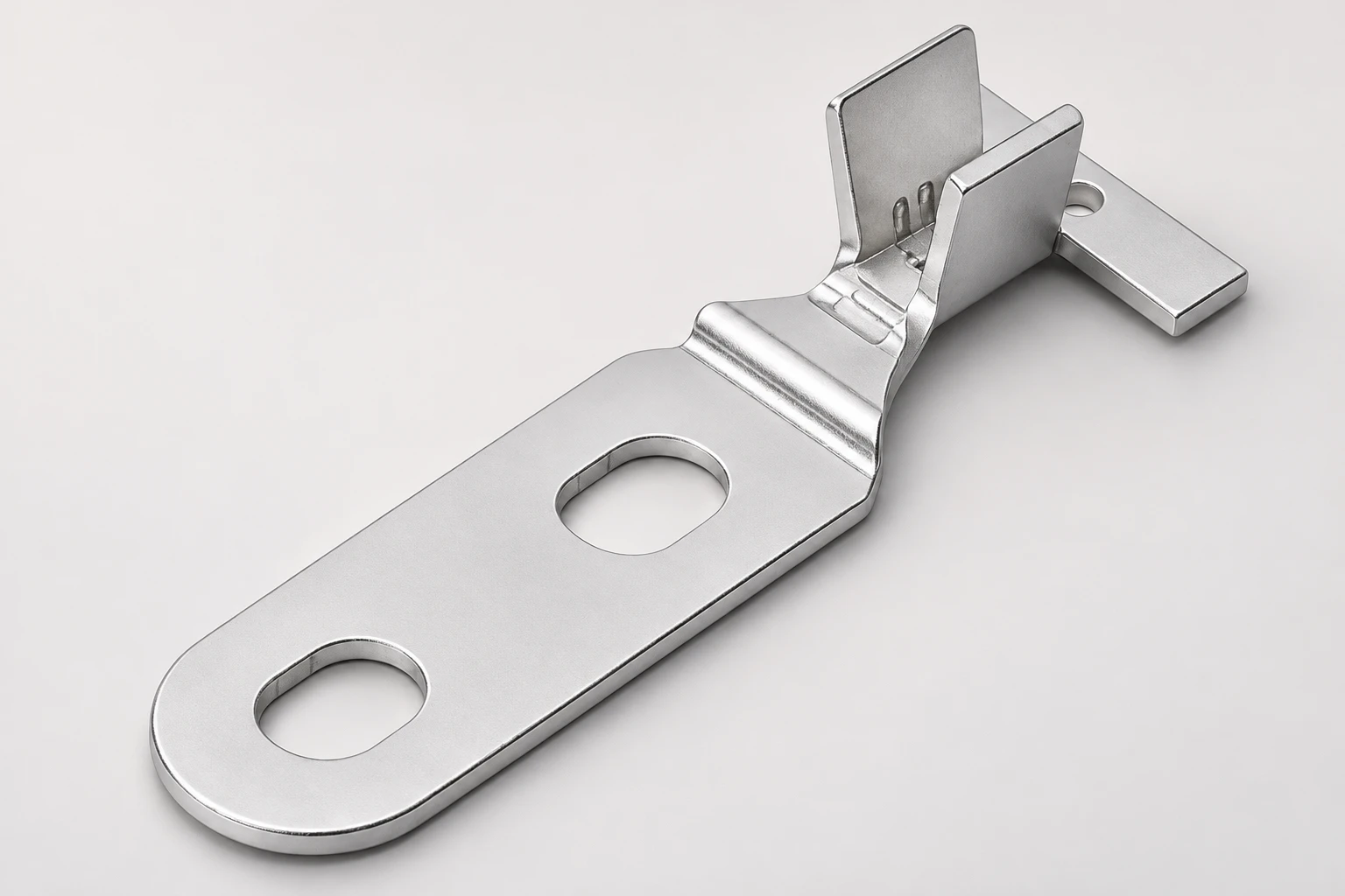
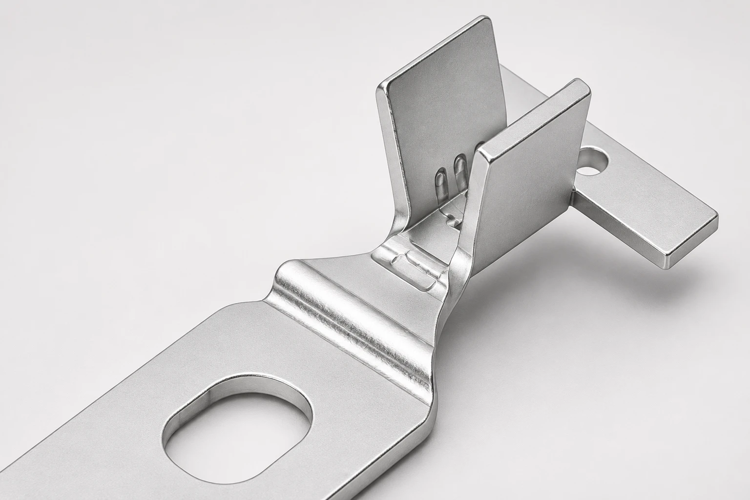
Shenji’s 349-YX terminal shows open termination wings and a two-hole palm. That product view helps identify the unformed features, but it is not a crimp-height specification. Before production, request the approved conductor range, tooling combination and final dimensional requirements. Do not infer a measurement value from the photograph or use the palm thickness as the crimp height.
Use the requirement for the exact terminal-wire combination
Record the terminal part number and revision, wire construction, conductor area and tooling identity. Include insulation details when they affect the termination configuration. A wire designation that omits strand construction or material may be too broad to establish the intended combination. Ask the application owner to resolve missing identification before setting an acceptance window.
The nominal value and tolerance should come from the released specification. If a supplier gives only a target without limits, ask how acceptance is determined. If two instructions disagree, clarify which revision controls the order. An operator should not have to decide between competing values at the inspection bench.
NASA research on inspection of crimped electrical connections treats crimp height as a mechanical measure within a wider investigation of connection quality. The work also considers failure conditions such as incomplete compression and partially inserted conductors. It supports using dimensions as part of a broader verification approach, not treating one reading as proof of every quality characteristic.
Keep tooling setup and product acceptance distinct
A press setting or tool adjustment is a process input. The measured crimp is an output. Recording that a machine was set correctly does not replace inspecting the resulting connection. Conversely, a single acceptable output does not establish that a drifting or damaged tool is under control. Keep both process settings and product measurements in the record.
Use the crimp-tool selection guide to establish compatibility, and the terminal and wire sizing guide to clarify conductor identification. These decisions precede measurement; a micrometer cannot compensate for a terminal-wire combination that was never approved.
Control the instrument and how it contacts the part
Select the measuring instrument and contact geometry required by the application instruction. Some terminal shapes need a dedicated crimp micrometer or comparator to reach the intended surfaces without including flash or adjacent features. A convenient flat-jaw measurement may span a different dimension. Do not assume that all instrument types produce interchangeable results.
Before inspection, confirm instrument identification, calibration status, measuring range and suitability for the tolerance. Check the reference or zero condition using the approved procedure. Keep measuring faces clean and inspect them for damage. If the instrument cannot resolve the required acceptance decision reliably, escalate the measurement problem before adjusting the crimp process.
| Control | What the instruction should state | Potential misleading result |
|---|---|---|
| Feature | Conductor barrel or other explicitly defined section | Insulation support measured instead |
| Location | Position along the formed barrel and orientation | Reading includes transition or cutoff region |
| Instrument | Contact geometry, range and verification method | Jaws bridge unwanted surfaces |
| Technique | Seating and measuring force according to procedure | Part rocked or compressed during measurement |
| Identification | Terminal, wire, tool, lot and revision | Reading compared with another combination |
| Disposition | Acceptance limits and response to abnormal readings | Values averaged to conceal a failed specimen |
This original checklist does not replace the application drawing. Its purpose is to ensure that different inspectors measure the same thing. Where the measurement method is unclear, use representative samples and a controlled comparison to resolve the technique. Record the agreed method rather than relying on one experienced operator’s memory.
Seat the terminal consistently and avoid measuring a specimen already distorted by a destructive test. If the same sample will undergo several inspections, define their order. A pull test or sectioning operation may change the feature needed for dimensional inspection. Keep the sample sequence visible in the laboratory instruction.
Separate measurement variation from process variation
If readings disagree, first confirm that the inspectors used the same location, orientation and instrument method. Repeated measurements at different positions can appear to show an unstable process when the measured feature was never held constant. A documented measurement study can help distinguish operator and instrument effects from differences between parts.
Then review the process record. Changes in wire, terminal lot, applicator, die condition, setup or feeding may deserve investigation. Do not assume every deviation can be corrected by closing the tool further. Adjusting a process without understanding the affected feature can create a different defect while bringing one number toward its target.
NASA-STD-8739.4A with Change 4 provides an example of a broader workmanship system combining controlled processing and verification. Its aerospace requirements apply within their defined scope; they do not assign a crimp height to an unrelated Shenji terminal. Use the project’s invoked requirements and approved application documents for the actual release decision.
Handle an out-of-limit reading as a controlled event
Record the actual value, sample identity and instrument before changing settings. Confirm whether the reading is valid using the approved measurement method. If it is a genuine product deviation, contain the related production according to the quality plan. Identify the process window and the last acceptable check rather than treating the next good specimen as proof that earlier material is acceptable.
After correction, make new representative samples and repeat the relevant inspections. Keep the original result and corrective action in the record. A report that overwrites the failed value with a retest loses the information needed to understand the event. If the cause remains uncertain, leave that uncertainty visible for the release owner.
Connect dimensions with visual, mechanical and electrical checks
Crimp height is a useful process characteristic, but it cannot establish conductor insertion, strand condition, terminal mating geometry and every electrical property by itself. The inspection plan should identify complementary checks and their acceptance documents. Do not add tests merely to create a longer checklist; select those needed to demonstrate the specified connection quality.
The broader terminal installation overview helps organize the complete assembly requirement. The terminal-retention inspection guide covers seating in the housing, which is separate from the measured barrel dimension. A dimensionally acceptable crimp can still require correction if the contact was damaged or incorrectly installed.
For a supplier submission, request individual readings or the agreed summary with the underlying data retained. Include the drawing revision, terminal and wire identity, tooling, instrument, sample selection and disposition. Ask the supplier to flag any deviation from the approved method. A generic certificate marked “dimension checked” does not show what was measured or why it passed.
For an original handover example, a first shift uses one wire lot and records acceptable measurements; the next shift changes wire reels. The handover should identify whether the change requires renewed setup verification under the quality plan. Carry forward the approved method and limits, but do not conceal the material change inside a continuous list of readings.
Keep the release package concise enough to use: a controlled measurement instruction, traceable results and a clear response to deviations. When the terminal, wire or tooling changes, review which parts of the evidence remain applicable. This is more dependable than collecting numbers without a stable definition of the product and method.
Measurement background: laboratory instruments
This IIT Kanpur-NPTEL laboratory lesson demonstrates dimensional measuring instruments, including micrometers. It is relevant background for instrument handling and reading. A terminal may require different measuring contacts and locations, so use its application instruction for the actual crimp-height method and acceptance limits.
Watch noc18-me62 Lec 12-Laboratory demonstration:Dial gauge and vernier,micrometer. on YouTube
Frequently asked questions
Can ordinary calipers always measure crimp height?
No. Use the instrument and contact geometry specified for the terminal’s measurement method.
Can one height apply to every wire size?
No. Use the approved requirement for the exact terminal, conductor and tooling combination.
Is insulation-crimp height the same as conductor-crimp height?
No. They refer to different features unless a specific drawing explicitly defines otherwise.
Does an acceptable height prove the complete connection is good?
No. Review the complementary visual, mechanical and electrical requirements in the quality plan.
What should happen when a reading is outside limits?
Record and validate the measurement, contain affected material, investigate the cause and verify the correction before release.






