

Copper busbar thermal expansion is the change in conductor length as its temperature changes. Review the available movement between supports, connected devices and mounting points before choosing an expansion feature or approving a thermal cycling test. A small calculated length change can still matter when a rigid assembly transfers it into a terminal, insulating support or bolted connection. The practical question is where that movement can go throughout the operating cycle. This guide explains a first movement estimate, the difference between free expansion and restraint, and the evidence buyers should request for an assembled electrical connection.
Start with a sketch of the whole movement path
A busbar is installed between other components. Draw those components together with their supports, mounting holes and intended connection surfaces. Mark which points are fixed, which can move, and which positions are uncertain. This sketch is usually more useful at the start than choosing a flexible component from a catalogue. It identifies whether expansion is mainly longitudinal, whether mounting surfaces move relative to one another, and whether cable forces add another load.
Separate the temperature of the conductor from the surrounding air. Electrical heating can produce a conductor temperature different from the enclosure ambient. Different portions of an assembly can also have different temperatures. For a first review, record the cold and hot conductor conditions and explain how they were estimated. A measured duty profile is stronger evidence than an assumed uniform enclosure temperature.
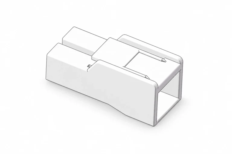
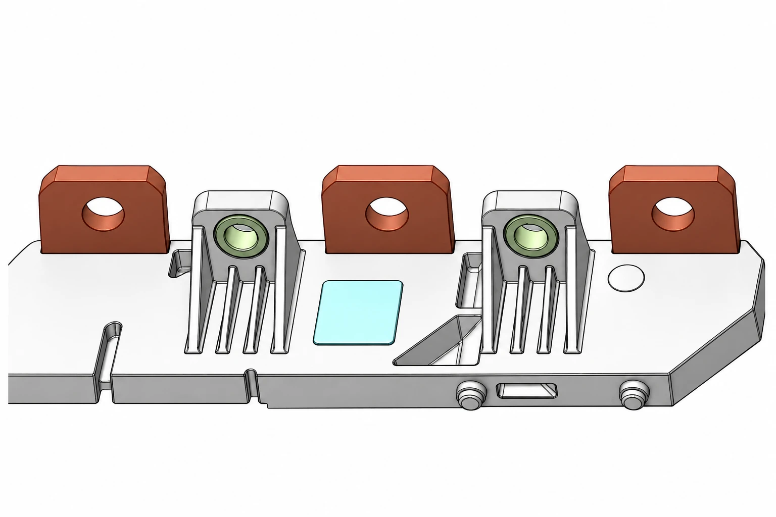
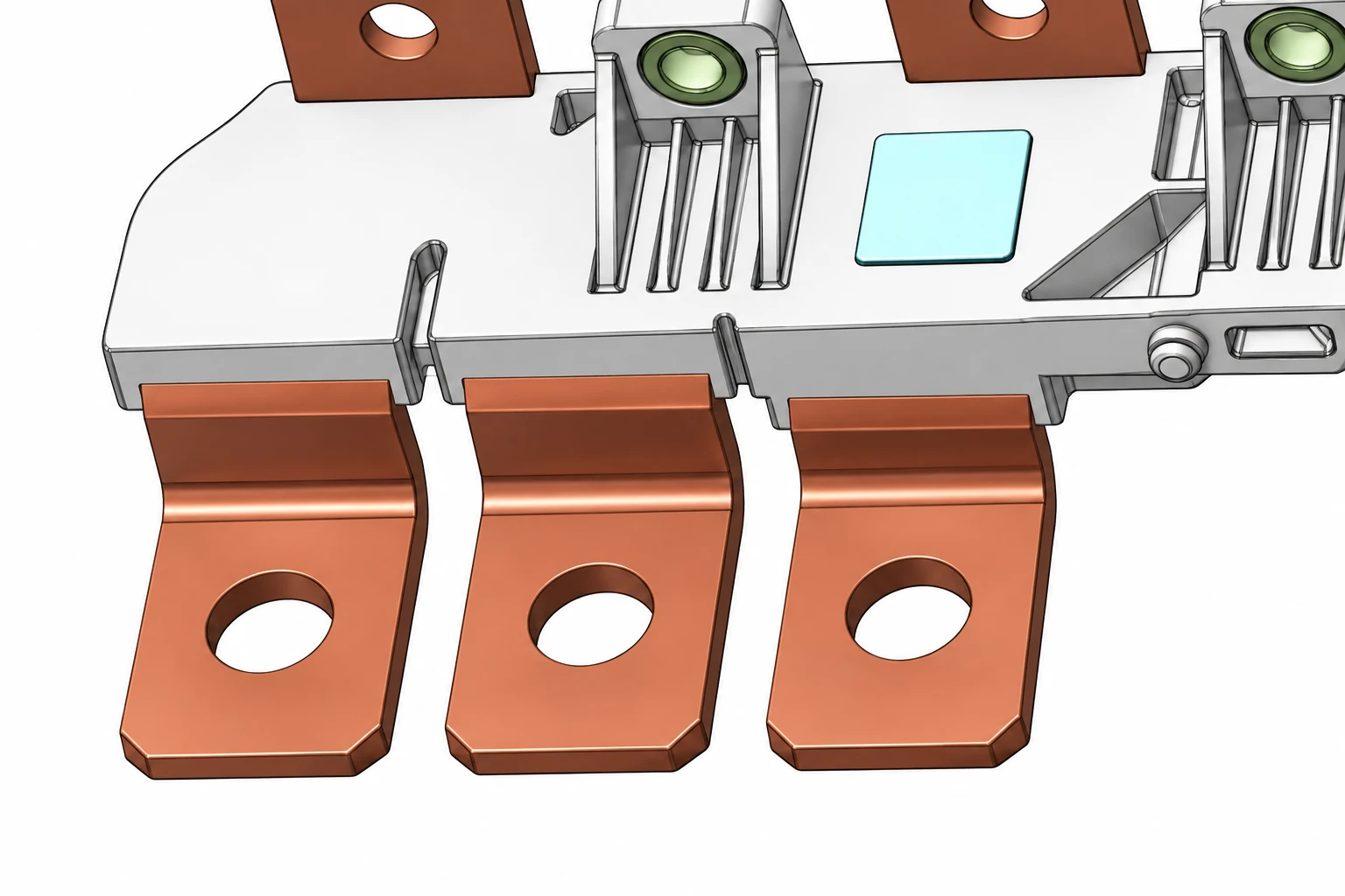
The illustrated BM001138 connection assembly offers a concrete way to discuss connection tabs, supporting features and nearby mounting interfaces. Its catalogue image does not establish a movement allowance or a thermal rating. Those requirements need an approved drawing and evidence for the selected assembly. For the broader construction choices, start with our electrical copper busbar overview.
Calculate a first estimate of free expansion
For a uniform straight conductor, a screening calculation is ΔL = α × L × ΔT. Here ΔL is the length change, α is the linear expansion coefficient, L is the initial length and ΔT is the conductor temperature change. Use consistent length units and a coefficient expressed per kelvin or per degree Celsius. A temperature difference has the same numerical value in those two scales.
For illustration, take a hypothetical 500 mm conductor, a temperature increase of 60 K and an assumed copper coefficient of 17 × 10−6 /K. The free movement estimate is 17 × 10−6 × 500 × 60 = 0.51 mm. This is an arithmetic example, not a dimension or performance value for BM001138. Confirm the appropriate coefficient for the actual material and temperature interval before using the result in design.
OpenStax explains the linear expansion relationship. Its simplified model assumes that material properties can be represented over the temperature interval. It provides a useful starting point; it cannot predict loads in a constrained, nonuniform assembly without additional information.
If a steel support and a copper conductor connect the same two positions, compare their movement rather than considering copper alone. In a simplified equal-length example, relative movement follows the difference between their coefficients multiplied by length and temperature change. Real supports may have different temperatures, lengths and constraints. Document those differences rather than silently applying the same conditions to every part.
Do not convert the estimated movement directly into bolt torque, allowable stress or service life. Those require stiffness, geometry, contact behavior, temperature-dependent material properties and the actual boundary conditions. If the estimate approaches an available clearance, request a detailed mechanical review before changing hole sizes or mounting details.
Decide where movement is permitted
There are two different questions: how much the conductor would expand freely, and what happens when the assembly restricts that expansion. A rigid restraint can convert displacement into force. A movable support may permit travel but still require controlled electrical spacing and mechanical guidance. A flexible section can accommodate some movement only within its specified directions and limits.
| Assembly condition | Evidence to request | Decision it supports |
|---|---|---|
| Two fixed connection points | Relative displacement and load assessment | Whether compliance is needed elsewhere |
| Sliding or guided support | Travel, clearances and retention drawing | Whether movement remains controlled |
| Flexible section | Approved movement directions and fatigue evaluation | Whether the proposed motion is within scope |
| Bolted electrical interface | Hardware stack and hot/cold connection evidence | Whether electrical contact remains stable |
| Insulating mounting feature | Temperature, dimensional and mechanical review | Whether the support preserves positioning |
This is a review checklist rather than a list of universal acceptance limits. The Copper for Busbars design guide discusses both movement along a conductor and temperature effects within connection hardware. Apply its principles with the requirements of the actual equipment.
For example, a slotted hole may look like an easy answer to a movement problem. Whether it is suitable depends on the electrical contact arrangement, bearing area, fastener retention and the intended sliding direction. Do not turn a joint intended to remain clamped into an uncontrolled sliding contact. Keep the mechanical movement solution and the electrical interface requirements consistent.
Similarly, a bend does not automatically make a rigid copper part an approved expansion connector. Ask whether the bend was designed for repeated movement, what strain range it sees and how its connections are supported. Our flexible copper busbar selection guide covers construction choices that should follow this movement assessment.
Make thermal cycling answer a defined question
A useful test plan starts with the failure mechanism being investigated. Chamber temperature cycling examines response to environmental changes. Current cycling adds heating through the electrical path. They can create different gradients and timing. Choose the method to represent the application, and record why its conditions are relevant. A cycle count without the temperatures, timing and assembly configuration provides little basis for comparison.
Before testing, identify specimens by drawing revision, material lot, surface finish and assembly record. Record the installed hardware and tightening procedure. Capture baseline photographs and agreed electrical measurements under defined conditions. Set acceptance criteria before collecting results so that a convenient outcome does not become a retrospective pass limit.
During the sequence, record the temperatures at locations that explain the behavior. A chamber air sensor alone may not show when the conductor, terminal and support have reached the intended conditions. The plan should identify stabilization or dwell rules, the measurement intervals and the handling of interruptions. Keep instrumentation placement consistent between specimens.
After the specified sequence, inspect movement-related damage and repeat the agreed measurements using comparable conditions. Examine connection surfaces, supports and mounting positions where the design review predicted loads. Compare electrical trends alongside physical findings. A change in resistance deserves investigation; it does not by itself identify the mechanical cause.
Our bolted busbar joint review addresses initial assembly and hardware evidence. The voltage drop diagnostic guide explains complementary electrical observations. Neither replaces a movement assessment or a qualified thermal test.
The following physics lecture provides background on thermal expansion. It supports understanding of the principle; the equipment test still needs its own documented conditions and acceptance requirements.
Watch Lec 32: Thermal Expansion | 8.01 Classical Mechanics, Fall 1999 (Walter Lewin) on YouTube
Ask for an assembly-specific evidence package
Send the supplier a marked drawing showing the fixed points, conductor path, attached equipment and available movement space. Include conductor temperatures, load profile and the expected number and frequency of operating changes. Identify whether the assembly also experiences vibration or installation misalignment. These inputs help separate normal thermal motion from a build problem that should be corrected elsewhere.
Request a written response that names the reviewed configuration and unresolved assumptions. If the supplier proposes a different support or flexible element, ask which movement it accommodates and how it changes the connected interfaces. A general statement that copper tolerates heat does not answer whether a particular assembly can tolerate constrained repeated displacement.
For test reports, compare the specimen drawing, mounting arrangement and electrical path with the part being purchased. Differences should be explained before a result is transferred. Retain the calculation, marked support sketch, test plan and final report together. That record makes a later change in enclosure size, mounting location or current profile easier to assess without repeating the entire investigation.
Frequently asked questions
How much does a copper busbar expand?
Estimate free movement with ΔL = α × L × ΔT, using the actual conductor length, temperature interval and an appropriate material coefficient. The result is a displacement estimate, not a load or life rating.
Does every busbar require an expansion joint?
No universal rule applies. Review length, temperature change, restraints, connected equipment and available compliance. A short rigid connection can still require attention if its mounting points move differently.
Can a slotted mounting hole solve thermal movement?
Only if the complete design permits that travel while preserving retention, electrical contact and spacing. Do not modify holes or allow sliding at a clamped contact without approval.
Is chamber cycling equivalent to current cycling?
No. They can produce different temperature distributions and timing. Select the method and measurements that address the expected service conditions and failure mechanisms.
What should a buyer request first?
Request the assembly drawing, fixed-point map, operating temperatures and proposed movement assessment. Then agree on the configuration, measurements and acceptance criteria for any validation test.