


A copper busbar bolted joint needs an approved assembly specification, not a torque value copied from a bolt chart. Contact surfaces, overlap, fasteners, washers, thread condition and the surrounding supports must be considered together. The practical goal is a stable electrical interface that remains mechanically secure throughout the intended service conditions. Before approving a joint, obtain the drawing, installation method and evidence that the complete connection meets the project’s electrical and thermal requirements.
This guide explains how buyers and engineers can review that evidence. It does not assign a tightening torque or current rating to an unidentified copper assembly. Work on power equipment belongs to qualified personnel using the equipment manufacturer’s isolation and installation procedures.
Start with the complete connection, including its supports
A joint is more than two pieces of copper and a bolt. Identify the contact faces, conductor thickness, hole pattern, available overlap and any insulating supports. Establish which parts carry current and which parts only retain or locate the assembly. A mounting screw into a plastic support may have a different purpose from a fastener clamping the electrical interface. Confusing those functions can lead to an unsuitable installation instruction.
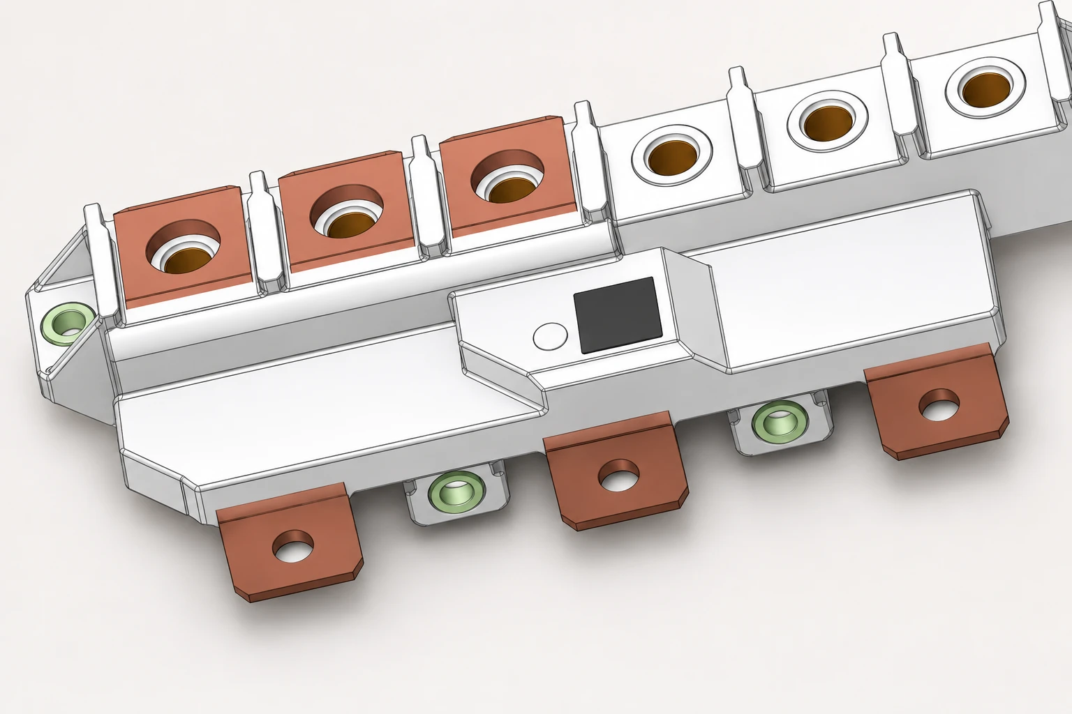
Record both mating parts by part number and revision. A photograph may show that a copper tab has a mounting hole, but it cannot establish the permitted fastener stack, bearing stress or tightening method. For example, Shenji’s BM001135 assembly provides a useful starting point for identifying an insulated multi-connection product. Its public image should be followed by an approved interface drawing before a bolted connection is designed.
Check the installation envelope as well. A wrench needs access without pressing against adjacent insulation or bending a terminal. Connected cables and bars need support that does not use the joint as an alignment tool. If assembly requires pulling a conductor into position, ask whether the resulting load was included in the design review. A joint that closes easily on a bench may behave differently after installation into a constrained enclosure.
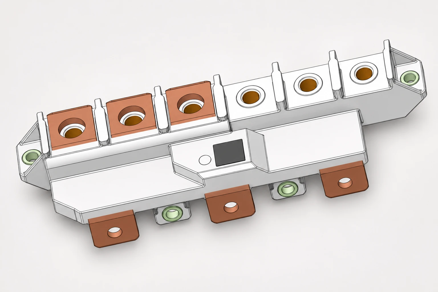
Why tightening torque is only part of the answer
The Copper Development Association’s Copper for Busbars guide explains the roles of interface pressure, current-flow geometry and bolting arrangements. Applied torque is used to develop fastener tension, which produces clamping force; friction and the condition of the fastening surfaces influence that relationship. Consequently, equal wrench settings do not establish equal interface pressure in different assemblies.
This is why a generic torque table cannot release a copper connection. Such a table may concern fastener strength while saying little about the copper, the contact footprint or an insulating component beneath the hardware. Adding lubricant, substituting a coated bolt or changing a washer can alter the installation condition. Any substitution should return to the assembly owner for review rather than being treated as a convenient shop-floor improvement.
Useful evidence also separates mechanical and electrical performance. A fastener can remain visibly in place while the electrical interface changes. Conversely, a low initial resistance reading does not prove that the clamp will remain stable through temperature changes and vibration. Ask how both aspects were assessed and whether the tested assembly matches the proposed production configuration.
A calculation needs controlled inputs
A simplified engineering relationship is T = K × F × d, where T is tightening torque in N·m, F is preload in N, d is nominal diameter in m, and K represents the torque factor for the defined fastening condition. As an arithmetic example only, K = 0.20, F = 1,000 N and d = 0.006 m produce T = 1.2 N·m. These invented example inputs are not an assembly recommendation.
The relationship explains sensitivity rather than supplying a safe setting. The engineer must justify preload, friction assumptions, material limits and uncertainty using the actual joint. Do not turn the example into a torque instruction, or substitute a factor from an unrelated coating and thread condition. The released assembly specification remains the controlling document.
What a usable joint specification should contain
The following table is an original document-review checklist, not a table of installation limits. Its purpose is to expose missing decisions before parts reach production. Each row should point to a controlled drawing, procedure or report rather than relying on an informal email description.
| Review item | Evidence to request | Reason to stop approval |
|---|---|---|
| Mating surfaces | Material, finish and permitted preparation for both sides | One side or its coating is unidentified |
| Hardware stack | Exact bolt, nut, washers, orientation and allowable substitutions | Installer chooses washers by appearance |
| Tightening method | Torque or other controlled method, thread condition, sequence and tool requirements | Value copied from a general bolt table |
| Mechanical support | Support locations and permitted interface loads | Fasteners must pull misaligned conductors together |
| Electrical validation | Measurement points, load conditions and acceptance criteria | Only a continuity beep is supplied |
| Traceability | Assembly revision, hardware lots and installation records | Test sample cannot be matched to the supplied configuration |
Surface preparation deserves explicit wording. An instruction to “clean the copper” leaves unanswered which material may be removed and which chemicals are compatible. Aggressive abrasion may damage an intentional finish. Require the approved process for the actual interface, including handling after preparation. Packaging and storage should prevent the prepared surface from becoming an uncontrolled variable before assembly.
Likewise, do not insert a spring washer, joint compound or locking product because it worked on another installation. Ask which function it serves, whether it is permitted at that location, and whether the test evidence includes it. Purchasing substitutions should identify the affected assembly and trigger a documented engineering decision.
Validate resistance and temperature under defined conditions
A BRIN-published experimental study investigated how pressure affected resistance and temperature in a particular overlapping copper connection. Its findings support treating pressure and electrical behavior together. Its sample geometry and loading conditions do not establish acceptance limits for other busbars or Shenji products.
For your project, request the measurement method, instrument identification and exact sensing locations. A measured voltage drop can include more than the intended interface if the sensing points extend along connecting conductors. Keep those locations consistent when comparing samples. Record current and temperature alongside the result, and distinguish a connection measurement from a measurement of the entire current path.
Thermal evidence should identify the enclosure, cooling conditions, adjacent heat sources and connected conductors. A free-air sample cannot automatically represent a densely packed installation. Define the intended operating profile and the acceptance criteria before testing, so that a convenient test arrangement does not quietly become the product requirement.
Evaluate change after conditioning
The relevant question is often whether the joint remains acceptable after the conditions expected in service. Ask which environmental or mechanical conditioning was selected, why it represents the application and what was measured before and afterward. Avoid translating a short laboratory demonstration directly into a service-life claim.
The public scope of NASA-STD-5020 on threaded fastening systems identifies design and analysis as part of fastening-system control. Its scope is spaceflight hardware, so it is not a busbar installation specification. For your connection, require an application-specific engineering review and keep the assembly configuration tied to the resulting installation and validation documents.
Turn the review into a clear purchase and release package
Include the equipment application, assembly drawing, mating conductor details, installation constraints and expected environment in the inquiry. Ask the supplier to identify missing data rather than assume a familiar configuration. If the public catalogue does not contain a torque instruction, record that omission and request the applicable document. Silence is not approval to select an installation value yourself.
Keep identification separate from performance evidence. The copper busbar identification guide helps establish part and lot traceability, while the broader copper busbar connection overview provides context for the assembly type. Use those records to make the review specific, not to infer an unlisted electrical rating.
For electrical diagnosis, read the voltage-drop measurement guide; for load-related conditions, consult the current-derating review. These are complementary questions. A joint torque instruction, a resistance result and a current-capacity assessment should agree on the same assembly configuration.
Before releasing a batch, have one person confirm that the drawing, hardware list, installation procedure and test report identify the same revision. Record unresolved exceptions with an owner and disposition. If a supplier proposes a replacement fastener or finish after approval, review the affected evidence before accepting the change. This prevents an otherwise complete package from becoming obsolete during procurement.
Physics background: torque
The following CrashCourse lesson explains rotational force and moment arms. It is useful background for understanding a torque wrench, but it does not provide busbar assembly settings or an electrical qualification method.
Watch Torque: Crash Course Physics #12 on YouTube
Frequently asked questions
Can I choose busbar torque from bolt diameter alone?
No. The approved setting depends on the complete connection, including materials, hardware stack and thread condition. Obtain the assembly-specific instruction.
Does higher torque always improve a copper connection?
No. Increasing torque without an approved basis may damage conductors, threads or supports. Validate the specified assembly rather than tightening until it feels secure.
Can a low initial resistance release the joint?
It is only one piece of evidence. Review mechanical security, measurement conditions and behavior after the conditioning required by the project.
Should plated copper be sanded before assembly?
Only follow the approved preparation method for that finish. Uncontrolled abrasion can remove a functional surface layer.
What should an inquiry include?
Include both mating parts, drawings, materials, hardware, installation access, operating environment and the electrical and thermal evidence you need.






